Making Things Interactive

May 1, 2008

Class Review

Filed under: Final Writing Assignment,Joshua Smith — jssmith44 @ 12:48 pm

 This is hands down one of my top two favorite course taken in college (the other, another course taught by Mark).  I dream of working in an industry where I can apply the skills I have gained in this course, and I look forward to applying interactive techniques in every project I do going forward.

That said, I have a few suggestions for how I might tweak the course for upcoming semesters. First off, I would consider assigning more specific projects at the beginning of the semester, and then working up to more open ended at projects at the end. I believe sometimes students get lost in the creative aspect of the early projects, and don’t necessarily grasp the specific technical processes that are supposed to be emphasized each week. This ensures that by the time the creative projects come around, all skills are in place.

Additionally, I would spend a number of classes demonstrating how to implement some advanced tasks, without going into to much detail on how and why they work. Such advanced topics include wireless communication, serial communication, graphically displaying data, camera recognition, etc. The reason for this is that these skills all have the power to greatly increase the scope of a students project, yet are not all that difficult to implement in different ways, once a student is shown how. 

Beyond that, I think the structure of the course is extremely conducive to the students’ success and I believe this will be demonstrated at our final show. Thank you Mark and Jet for a great semester!

March 28, 2008

Simon Says: Macbook Tilt Edition

Filed under: 8: State Machine,Joshua Smith — jssmith44 @ 2:08 pm

Below is the processing code for the Simon Says game I made involving tilting your macbook along different axis. Im going to build a better GUI for it, and update the code with it soon.

import sms.*;

int gameSize = 100; //max sequence number
int[] gameSeq = new int[gameSize]; // generated sequence (0,1)
int level = 0;
int threshold = 100; // threshold value for tilt sense
int currentX = 0; // current state of tilt (0, 1, -1)
int lastX = 0; // last state of tilt
int userIndex = 0; // where player is in sequence
int displayState = 0; // should display sequence?

void setup() {
size(600,600);
stroke(255);
generateSequence();
}

void draw() {
background(0);
int[] vals = Unimotion.getSMSArray();
//println(vals[0] + ” ” + vals[1] + ” ” + vals[2]);
lastX = currentX;
if (vals[0] > threshold)
currentX = 1;
else if (vals[0] < (threshold *-1)) currentX = -1; else currentX = 0; if(displayState == 0) displaySequence(); // show values up to index, then say go! if(detectChangeEvent() && currentX != 0) evaluate(); } void evaluate() // determine if move matches sequence { if(currentX == 1 && gameSeq[userIndex] == 1){ flashCorrect(); if(userIndex < level) userIndex++; else {displayState = 0; level++; userIndex=0; currentX = 0; println(); println("Round: " + (level+1)); delay(2000);} } else if(currentX == -1 && gameSeq[userIndex] == 0){ flashCorrect(); if(userIndex < level) userIndex++; else {displayState = 0; level++; userIndex = 0; currentX = 0; println(); println("Round: " + (level+1)); delay(2000);} } else reset(); } void displaySequence() // show sequence up to userIndex { for(int i =0; i

March 25, 2008

Physically Building Virtual Worlds – Proposal

Filed under: Final Project,Joshua Smith — jssmith44 @ 11:53 am

The Concept:A child is given a set of physical scaled Models( Ex: Buildings, Sky Scrapers, Bridges, Monsters, Boats, People, etc)The child can then create their own virtual world by arranging a set of their models within a given square on a table, and their virtual world model is automatically rendered in Google SketchUp for them to explore in more detail.Parts List:

  • Table with Glass Square
  • Camera
  • Scaled Models (either purchased or made from craft material)-
  • Processing Computer
  • Fiducial Stickers

Technical Specifics: The only real hardware component to this project will be a camera and glass table. The rest is mainly software based. A camera will be mounted under the table, facing upwards. Each object will have its own fiducial ( see examples below) sticker on its base, so using the camera… its absolute position and orientation can be registered using an Open-Source Fiducial Recognition Framework. The application will then pass these position and orientation values to a Google SketchUp file preloaded with the coresponding digital models for each physical model. SketchUp will then render the world based on the position and orientation values. There will also be a space in the upper corner of the table, for a child to pick materials. For instance they can put a Grass Square in the upper corner, for the world to be built on grass, or water, etc. The system will completey expandable, so that as long as someone wants to build their own physical model, and corresponding digital model, any environment can be rendered.Fiducial Example: fiducial1I am also considering creating this same model with 3 cameras instead of 1. This would allow the software to recognize not just the absolute position on the x axis, but on the Y and Z as well, so a child could place buildings on top of one another. Below is a basic state diagram:PhysWorld State Diagram
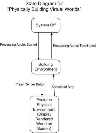
Specific Software List:ProcessingreacTIVisionFrameworkRuby SketchUp APIFurther Down The Road: Rather then just build a snap shot of a Virtual World at one point, children could use this to script and direct their own movies. They could press a record button, and it would record the moving of their boat from point A to B, and then the person getting out of the boat and walking into the building. Add the functionality of recording sound, and they can create some great movies very simply.

March 19, 2008

State Diagram For RPSATO

Filed under: 8: State Machine,Joshua Smith — jssmith44 @ 8:55 pm

Below is the state diagram for a Bickering-Free, Definitive way to solve a a disagreement across a distance…. Remote Rock Paper Scissor.

rpsato_state_diagram.jpg

I may pursue this for my final project, but not the entire system by next week.

March 10, 2008

Physical Pixel Representation – Bridging the gap between my Computer and the Physical World

Filed under: 5: Making Motion,Joshua Smith — jssmith44 @ 3:05 pm

For this project, I wanted to investigate bridging the gap between my computer and the physical world. I split my computer screen into 6 white squares ( a 3 x 2 matrix). I then created a physical representation of these squares with a 3 x 2 matrix of Red Led’s.  The physical matrix represents which square my mouse is within the screen. As the mouse moves into a new square, that square turns red on the screen and the corresponding LED turns on. This system consisted of a Processing Application to determine where the mouse was on the screen, run the screen display, and pass that location on to the Arduino Program using serial communication. The Arduino program then controlled the physical pixel matrix. Video is below: (Video Here) Processing Code:  

import processing.serial.*;

Serial port;
String colorO = “#FFFFFF”;
String colorC = “#FF0000”;

void setup()
{
size(900, 600);
noStroke();
frameRate(10);

// List all the available serial ports in the output pane.
// You will need to choose the port that the Arduino board is
// connected to from this list. The first port in the list is
// port #0 and the third port in the list is port #2.
println(Serial.list());

// Open the port that the Arduino board is connected to (in this case #0)
// Make sure to open the port at the same speed Arduino is using (9600bps)
port = new Serial(this, Serial.list()[0], 9600);
}

// function to test if mouse is over square
boolean mouseOverRectA()
{
return ((mouseX >= 0)&&(mouseX = 0)&(mouseY = 301)&&(mouseX = 0)&(mouseY = 601)&&(mouseX = 0)&(mouseY = 0)&&(mouseX = 301)&(mouseY = 301)&&(mouseX = 301)&(mouseY = 601)&&(mouseX = 301)&(mouseY <= 600)); } void draw() { background(#FFFFFF); stroke(255); line(0, 295, 700, 295); strokeWeight(2); if(mouseOverRectA()) // if mouse is over square { fill(#FF0000); // change color port.write('A'); // send an 'H' to indicate mouse is over square } else { fill(#FFFFFF); // change color port.write('B'); // send an 'L' otherwise } rect(0, 0, 300, 300); // draw square if(mouseOverRectB()) // if mouse is over square { fill(#FF0000); // change color port.write('C'); // send an 'H' to indicate mouse is over square } else { fill(#FFFFFF); // change color port.write('D'); // send an 'L' otherwise } rect(300, 0, 300, 300); // draw square if(mouseOverRectC()) // if mouse is over square { fill(#FF0000); // change color port.write('E'); // send an 'H' to indicate mouse is over square } else { fill(#FFFFFF); // change color port.write('F'); // send an 'L' otherwise } rect(600, 0, 300, 300); // draw square if(mouseOverRectD()) // if mouse is over square { fill(#FF0000); // change color port.write('G'); // send an 'H' to indicate mouse is over square } else { fill(#FFFFFF); // change color port.write('H'); // send an 'L' otherwise } rect(0, 300, 300, 300); // draw square if(mouseOverRectE()) // if mouse is over square { fill(#FF0000); // change color port.write('I'); // send an 'H' to indicate mouse is over square } else { fill(#FFFFFF); // change color port.write('J'); // send an 'L' otherwise } rect(300, 300, 300, 300); // draw square if(mouseOverRectF()) // if mouse is over square { fill(#FF0000); // change color port.write('K'); // send an 'H' to indicate mouse is over square } else { fill(#FFFFFF); // change color port.write('L'); // send an 'L' otherwise } rect(600, 300, 300, 300); // draw square }[/sourcecode] Arduino Code [sourcecode language='cpp'] int outputPin = 13; int val; void setup() { Serial.begin(9600); pinMode(outputPin, OUTPUT); } void loop() { if (Serial.available()) { val = Serial.read(); if (val == 'A') { digitalWrite(2, HIGH); } if (val == 'B') { digitalWrite(2, LOW); } if (val == 'C') { digitalWrite(3, HIGH); } if (val == 'D') { digitalWrite(3, LOW); } if (val == 'E') { digitalWrite(4, HIGH); } if (val == 'F') { digitalWrite(4, LOW); } if (val == 'G') { digitalWrite(5, HIGH); } if (val == 'H') { digitalWrite(5, LOW); } if (val == 'I') { digitalWrite(6, HIGH); } if (val == 'J') { digitalWrite(6, LOW); } } } [/sourcecode] Hardware: Each LED is directly connected to Digital Pins 1-6 and Ground.

March 9, 2008

NoseTouch Sensor

Filed under: 7: Mid-Term Project,Joshua Smith — jssmith44 @ 8:29 pm

For this project I created a system that follows an individual when in the camera’s field of vision, and detects when the user touches his/her nose. Video is displayed below:The project consists of a Processing application (processing.org), an Arduino application (arduino.cc), and a hardware component.  The computer vision component is processed in the Processing application and the user’s physical location and state (nose touch or no touch) is passed to the Arduino application which drives the hardware.   The following Processing code uses the OpenCV framwork (http://www.intel.com/technology/computing/opencv/) and the Face Detect Library for Processing by Jaegon Lee (http://tokage.cafe24.com/facedetect/)  

import FaceDetect.*;
import processing.serial.*;  

FaceDetect fd;
Serial port;

int viewingAngle = 75;  //Camera's Viewing Angle
int MAX = 4;            // Max number of faces detected at once (for game)
int sPosition = 90;     //servo starting position

int[] x = new int[MAX];
int[] y = new int[MAX];
int[] r = new int[MAX];
int[][] Faces = new int[MAX][3];

void setup(){

  size(640,480);
  fd = new FaceDetect();
  fd.start(width,height, 10);
  println(fd.version()); 
  
 
  noStroke();
  println(Serial.list()); // List COM-ports

  //select second com-port from the list
  port = new Serial(this, Serial.list()[0], 19200); 
}

void draw(){
  background(0);

  Faces = fd.detect();
  int count = Faces.length;
  
   
  if (count>0) {
    for (int i = 0;i<count;i++) {
      x&#91;i&#93; = Faces&#91;i&#93;&#91;0&#93;;
      y&#91;i&#93; = Faces&#91;i&#93;&#91;1&#93;;
      r&#91;i&#93; = Faces&#91;i&#93;&#91;2&#93; * 2;
 println(i+1 + ": " + x&#91;i&#93;+", "+y&#91;i&#93; + ", " + r&#91;i&#93;);
 

  int divider = (width)/viewingAngle;  
  int sPosition= x&#91;i&#93;/divider;  //Calculate servo postion from Face X Coordinate
  sPosition = sPosition - (sPosition%1);


  //Output the servo position ( from 0 to ViewingAngle)
  port.write("s"+sPosition); 

    }
  
  }

    
  int&#91;&#93; img = fd.image();
  loadPixels();
  arraycopy(img,pixels);
  updatePixels();

 if (count == 0)  //identifies nose touch (no faces recognized)
    {port.write("w"); 
   delay(250); }

  strokeWeight(2);
  stroke(255,200,0);
  noFill();
  for(int i =0;i<count;i++) {
    ellipse(x&#91;i&#93;,y&#91;i&#93;,r&#91;i&#93;,r&#91;i&#93;);
  }
  
 
}

public void stop(){
  fd.stop();
  super.stop();
}

&#91;/sourcecode&#93;

  <span style="font-family:Verdana;font-size:13px;line-height:18px;white-space:pre-wrap;" class="Apple-style-span">The Arduino code to communicate with the processing code and drive the servo motor and LED eyeball: (note this code requires installation of the Arduino "Servo" library)</span>  


#include 
Servo servo1; 
int ledPin = 13;

void setup() {
  servo1.attach(14);
  servo1.setMaximumPulse(2500);
  Serial.begin(19200);
  Serial.print("Ready");
}
void loop() {
  static int v = 0;
  if ( Serial.available()) {
    char ch = Serial.read();
    switch(ch) {
      case '0'...'9':
        v = v * 10 + ch - '0';
        break;
      case 's':
        servo1.write(v);
        v = 0;
        break;
        
      case 'w':
      blink();
      v = 0;
      
      
    }
  } 

 Servo::refresh();
}

void blink(){
  digitalWrite(ledPin, HIGH);   // sets the LED on
      delay(100);                  // waits for .1 second
      digitalWrite(ledPin, LOW);    // sets the LED off
      delay(100);                  // waits for .1 second
    }

(the include file should be “Servo.H”, but I cant get it to show up in the sourecode editor)

Finally, the hardware component consisted of just an aluminum rod, rubber eyeball, red LED, and a servo motor. The Servo motor was connected directly to the Arduino board in the following manner: Orange: 5V; Black: Ground; Yellow: Analog Input 0;
The Led was connected to Ground and Digital Pin 13.  

February 5, 2008

Arduino Event Timer

Filed under: 4: Counting Sensor Input,Joshua Smith — jssmith44 @ 1:41 pm

I wanted to write a program that would allow the Arduino to calculate the duration of an event. For instance, to be able to display how long a window has been open, or how long your dog has been lying on her pillow bed when you come home, etc. The following code is based on a simple switch with the following circuit diagram:Switch Circuit DiagramWhen the switch is put in the closed position, the Arduino begins counting seconds until the switch is opened. The seconds are then converted to “hours:minutes:seconds” format and passed back and displayed on the terminal using my displayDuration() function. Once the switch is opened, the timer is reset and can begin all over again.For the code to work correctly, I had to calibrate the program to my computer. To do this I had to calculate how many milliseconds it took my computer to process each iteration of the main loop and then set the “offSet” variable equal to that. This was mainly a trial and error process, initiating the switch at the same time as a real stopwatch and making adjustments so they matched up. 

#include 
Servo servo1; 
int ledPin = 13;

void setup() {
  servo1.attach(14);
  servo1.setMaximumPulse(2500);
  Serial.begin(19200);
  Serial.print("Ready");
}
void loop() {
  static int v = 0;
  if ( Serial.available()) {
    char ch = Serial.read();
    switch(ch) {
      case '0'...'9':
        v = v * 10 + ch - '0';
        break;
      case 's':
        servo1.write(v);
        v = 0;
        break;
        
      case 'w':
      blink();
      v = 0;
      
      
    }
  } 

 Servo::refresh();
}

void blink(){
  digitalWrite(ledPin, HIGH);   // sets the LED on
      delay(100);                  // waits for .1 second
      digitalWrite(ledPin, LOW);    // sets the LED off
      delay(100);                  // waits for .1 second
    }

Blog at WordPress.com.