May 14, 2008
Final Project: PhytoBot “Augmenting Plant Behavior Through Robotics”
The PhytoBot is a semi-intelligent plant which responds to external stimulus (light intensity and light location) and responds to it as a phototropic plant would. Essentially it is designed as a piece of interactive artwork for operation over a long period of time. The motivation driving this was triggered by the lack of understanding & acceptance of plants as reactive living organisms. Many of us are so used to placing life on merely objects that have visual and audible external responses which can be seen by the naked eye. Plants on the other hand tend to be overlooked as their responses are more drawn out over time and hence we tend to see them as inanimate objects.
The PhytoBot has two degrees of freedom and motion, rotational and angular (from the normal). The rotational range of motion is 360 degrees whereas the vertical/angular range is approximately 70 degrees. The second component of the response is the pulsing lights on the face. The lights pulse from on to off in a smooth glowing fashion as if the plant was breathing. The variance in frequency is driven by the amount of light given to the plant. A fast pulse indicates that the plant is healthy, and a slow pulse indicates that the plant is in need of more light. There are two basic mechanical features within the PhytoBot. When the PhytoBot actively seeks light, it is oriented by two servos in the x and y axes. When the light has been located the plant will twitch depending on how far away the light source is. For example a closer point light will produce more twitching than if the Plant was facing the sun.
Parts List:
– Plastic Laser Cut Structural Parts
– Foam Petals
– Foam core Box
– 4 Photo sensors
– 1 Green LED
– Wire (Solid core Flexible)
– Cable Wire
– 1 Standard Servo
– 1 Continuous rotation servo
– Screws
– 1 Arduino Microcontroller
– 4 100kOhm resistors
– Circuit boards for soldering components
– Acrylic glue
How it is Built: The PhytoBot is built primarily from laser cut acrylic parts. It was paramount to have my parts laser cut as they needed to fit correctly with minimal error. The whole plant can be divided up into 4 segments, the fixed base, rotating housing, stem and face. Each segment has their specific application and all working together complete the PhytoBot. The fixed base houses the rotational servo which in turn rotates the whole rotating housing. The rotating housing contains the stem servo. This stem servo is attached to the face via a cable wire through the stem. The stem supports the plant as it stands erect and also provides just the right amount of resistance to allow the plant to return to its erect position when not being pulled down. The face contains all the sensors and lights which provide the input and outputs of the whole plant. All the parts barring the petals were glues together using acrylic glue. This provided a strong hold and minimal movement/slop between the moving components.
Currently Im working on making a complete days time lapse video of my plant. Its a lot harder than I thought so the video isnt up as yet
May 12, 2008
The Light-o-Stat
Hello All:
Please take a look at my final term paper for my Light-o-Stat Project by following the attached link.
The majority of my documentation can be seen in the paper, but here are some other things too.
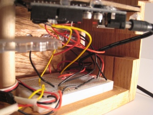
The Guts of the Project: The Mess that I made with an Arduino and Breadboard
int servoPin = 2;     // Control pin for servo motor
int minPulse = 800;   // Minimum servo position
int maxPulse = 2300;  // Maximum servo position
int neutralPulse = 1500;  //neutral servo
int pulse = 0;        // Amount to pulse the servo
int prevPhotosensor;  //last reading of sensor-last state
int increment = 50;   //pwm changes
int goodLED= 6;
int darkLED= 7;
int brightLED = 5;

long lastPulse = 0;    // the time in milliseconds of the last pulse
int refreshTime = 20; // the time needed in between pulses

int photoSensor = 0;  // the value returned from the analog sensor
int sensorPin = 1;    // the analog pin that the sensor's on
int average = 10;      // reads per cycle
int potSwitch = 0;     //potentiometer switch
int potMin = 0;
int potMax = 0;
int potPin = 0;

void setup() {
  pinMode(servoPin, OUTPUT);  // Set servo pin as an output pin
  pinMode(potSwitch, INPUT);
  pinMode(goodLED, OUTPUT);
  pinMode(darkLED, OUTPUT);
  pinMode(brightLED, OUTPUT);
  pulse = neutralPulse;           // Set the motor position value to the minimum
  digitalWrite(goodLED, LOW);
  digitalWrite(darkLED, LOW);
  digitalWrite(brightLED, LOW);
  Serial.begin(9600);

}

void loop() {
  delay(100);
  int x;
  int photoTotal;
  photoTotal = 0;
  for (x = 0; x<average; x++) {
    photoSensor = analogRead(sensorPin);      // read the analog input
    potSwitch = analogRead(potPin);         //pulse = (photoSensor *19)/10 + minPulse;
    photoTotal = photoSensor + photoTotal;  // convert the analog value
  }
  photoSensor = photoTotal/average;   //average of photo sensor readings

  potMin = potSwitch-25;
  potMax = potSwitch+50;

  Serial.print("Amount of Light = ");
  Serial.println((int)photoSensor);
  Serial.print("Desired amount of light = ");
    Serial.println((int)potSwitch);

  if (millis() - lastPulse >= refreshTime) {
    digitalWrite(servoPin, HIGH);   // Turn the motor on
    delayMicroseconds(pulse);       // Length of the pulse sets the motor position
    digitalWrite(servoPin, LOW);    // Turn the motor off
    lastPulse = millis();           // save the time of the last pulse
  }

  //good State
  if(photoSensor <= potMax && photoSensor >= potMin){  //if light value is in desired range, do the following
    digitalWrite(goodLED, HIGH);
    digitalWrite(darkLED, LOW);
    digitalWrite(brightLED,LOW);
    Serial.println("Light is good");
    //do nothing with pulse;
  }
  // bright State
  if(photoSensor < potMin){   // if the actual light is greater than desired, do this...remember that the values are reversed, larger number=darker and smaller number = brighter
    digitalWrite(goodLED, LOW);
    digitalWrite(darkLED, LOW);
    digitalWrite(brightLED,HIGH);
    Serial.println("Too Bright");

    //pulse clockwise
    if(prevPhotosensor > photoSensor) {  // if moving the shades makes it darker, it i doing the right thing, continue in this direction
      prevPhotosensor = photoSensor;
      pulse = pulse - increment;
      if (pulse < minPulse)
        pulse = minPulse;
    }

  }

  // dark State
  if(photoSensor > potMax){              // if level of light is below the minimum desired, it is too dark
    digitalWrite(goodLED, LOW);
    digitalWrite(darkLED, HIGH);
    digitalWrite(brightLED,LOW);
    Serial.println("Too Dark");
    //pulse counter-clockwise
    if(prevPhotosensor < photoSensor) {   //if moving the shades makes it lighter, it is doin the right thing
      prevPhotosensor = photoSensor;
      pulse = pulse + increment;
      if (pulse > maxPulse)
        pulse = maxPulse;
    }

  }
}

<pre>


You must be logged in to post a comment.